Intro
My SL-880’s electronics have slowly been dying since I got it used in 2011. At first you would have to turn it on and off a few times before it would work, after a few years this became a few dozen times, recently I couldn’t get it to work after 100 times and started looking for a replacement.
I settled on MIDIbox KB since I couldn’t really find a lot of details about the key bed on this model and MIDIbox KB offers a lot of options to work with diverse and weird setups. I didn’t like the modularity of the boards available for sale, so I decided to make my own.
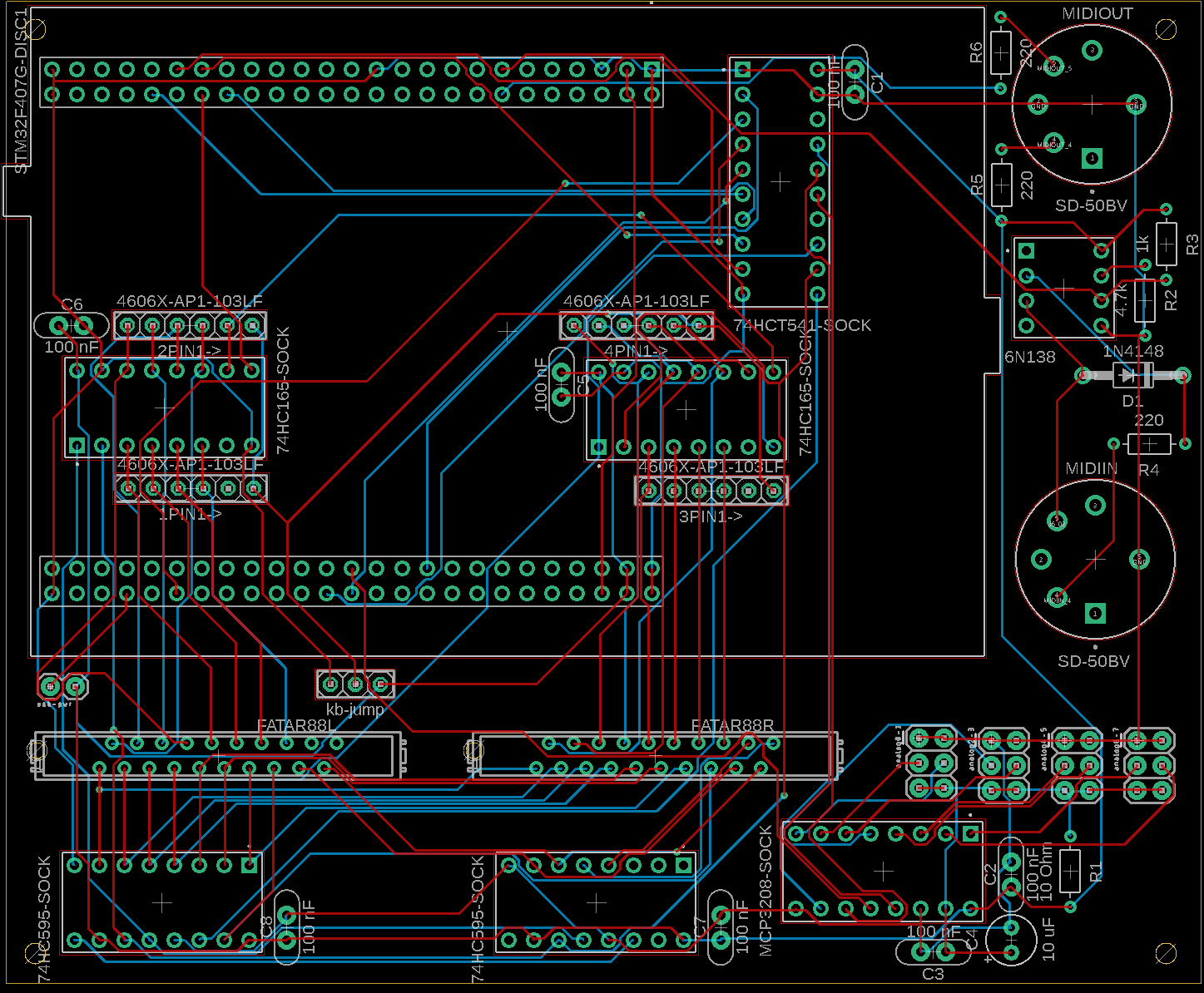
Using MBHP_CORE_STM32F4 as my core I designed a 2-layer board that combined it with MBHP_DIO_MATRIX, MBHP_AINSER8, and half MBHP_MIDI_IO in Autodesk Fusion. I sent it to JLCPCB for FR4 fabrication.
Board
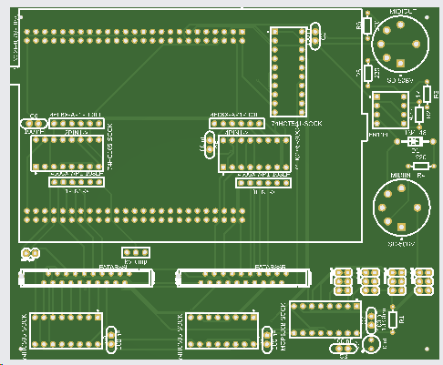
Note that the rest of the board images and files are a revision from what I had fabricated and has not been tested. Leave a comment if you want the original (the labeling of the AIN pins is wrong, and you need a custom build to use the 2nd AIN module). I’m not actually using 4 of the AIN and the MIDI so if I was to make another revision, I would take those off and squish the board down a little bit. I’d also add a place to put in pull-up or -down resistors on the AINs.
Fusion Archive
Gerber
High-res board image for assembly
Parts
This is a bit chaotic, but hopefully it helps. I used IC sockets but they aren’t really necessary.
| symb | quant | desct | package | label | part | digikey part |
| 1PIN1->, 2PIN1->, 3PIN1->, 4PIN1-> | 4 | 4606X-AP1-103LF | 4606X-AP1-103LF | 4606X-AP1-103LFCT-ND | ||
| C1, C2, C3, C5, C6, C7, C8 | 7 | Capacitor – Generic | CAP-THRU-2.54MM | 100 nF | 478-3193-nd | |
| C4 | 1 | Capacitor Polarised – Generic | CAPPRD254W65D500H1150B | 10 uF | mouse r 871-b41827a6106m000 | |
| D1 | 1 | Diode Rectifier – Popular Parts | DO41-10 | 1N4148 | 1N4004 | 4878-1N4004CT-ND |
| J1 | 5 | Check availability | AMPHENOL_DILB16P-223TLF | 16p ic socket | 2057-ICS-316-T-ND | |
| J2 | 12 | Multi connection point. | 2X3 | 2 row header | 609-10063545-400HLFCT-ND | |
| J6 | 1 | Check availability | AMPHENOL_DILB8P-223TLF | 8p ic socket | 2057-ICS-308-T-ND | |
| J7 | 5 | Multi connection point. | 1X02 | 1 row header | 609-77311-418-00LFCT-ND | |
| MIDIIN, MIDIOUT | 2 | Check availability | CUI_SD-50BV | SD-50BV | CP-3150-ND | |
| R1 | 1 | Resistor Fixed – ANSI | RESAD724W46L381D178B | 10 Ohm | 10qbk-nd | |
| R2 | 1 | Resistor Fixed – ANSI | RESAD724W46L381D178B | 4.7k | 4.7kqbk-nd | |
| R3 | 1 | Resistor Fixed – ANSI | RESAD724W46L381D178B | 1k | 1.0kqbk-nd | |
| R4, R5, R6 | 3 | Resistor Fixed – ANSI | RESAD724W46L381D178B | 220 | 10qbk-nd | |
| U$1 | 1 | AMPHENOL_DILB20P-223TLF | 20p ic socket | 2057-ICS-320-T-ND | ||
| U$6 | 2 | MICROMATCH-20 | 2-338068-0 | A99499CT-ND | ||
| U1 | 1 | Check availability | MODULE_STM32F407G-DISC1 | STM32F407G-DISC1 | STM32F407G-DISC1 | 497-16287-ND |
| 1 | MCP3208 | MCP3208-CI/P-ND | ||||
| 1 | 6N138 | 160-1795-ND | ||||
| 1 | 74HCT541 | 296-1619-5-ND | ||||
| 2 | 74HC165 | 296-12790-5-ND | ||||
| 2 | 74HC595 | 296-33112-5-ND | ||||
| 2 | 25×2 femail header | S9201-ND |
MIDIbox KB settings
set kb 1 note_offset 21
set kb 1 rows 12
set kb 1 velocity on
set kb 1 optimized on
set kb 1 dout_sr1 1
set kb 1 dout_sr2 2
set kb 1 din_sr1 1
set kb 1 din_sr2 2
set kb 1 din_key_offset 40
set kb 1 din_inverted off
set kb 1 break_inverted off
set kb 1 delay_fastest 50
set kb 1 delay_slowest 1000
set kb 1 make_debounced on
set kb 1 ain_pitchwheel 128
set kb 1 ctrl_pitchwheel 128
set kb 1 ain_modwheel 129
set kb 1 ctrl_modwheel 7
set kb 1 ain_expression 130
set kb 1 ctrl_expression 129
set kb 1 ain_sustain 131
set kb 1 ctrl_sustain 64
Cable attachment
The key cable ribbon from the left goes to the left and right to right.
I put the pitch wheel on the leftmost AIN pin my colors were
- purple (goes to contact on both wheels) = 5v (closest to edge)
- blue (goes to casing of both wheels) = ground (closest to center of board)
- grey (goes just to pitch wheel) = signal (between 5v and ground)
The mod wheel (used for volume) I put next and shares the 5v and ground of the pitch wheel so only
- green (goes just to mod wheel) = signal
The channel aftertouch I put next, the two signals have to be combined together, the pinout probably doesn’t matter as long as 5v goes to both ribbon cables and signal combined goes to both as well. Consider using a pull-down resistor.
- white = 5v
- yellow = 5v
- blue + black = signal
Last, I bought a 6.35mm TS jack with pigtail for my sustain pedal; one wire goes to 5v the other goes to signal, doesn’t really matter which, but the tip should be 5v really. Consider using a pull-down resistor.
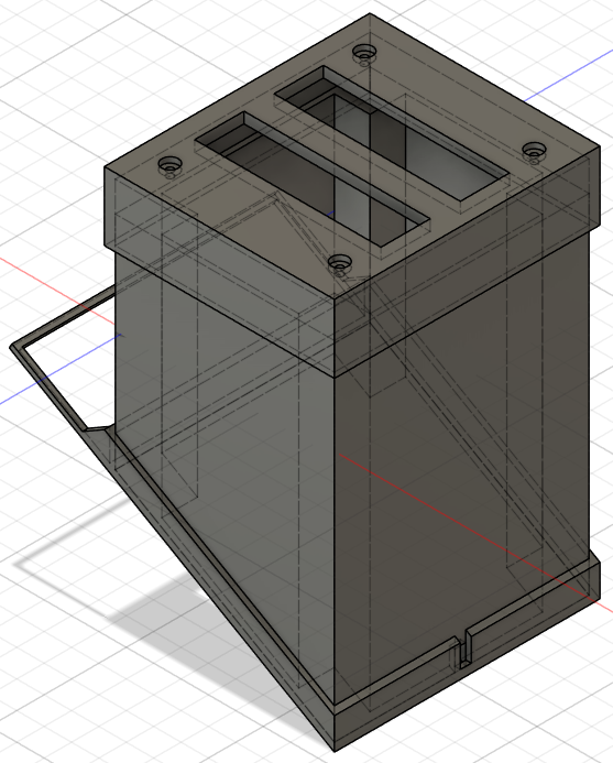
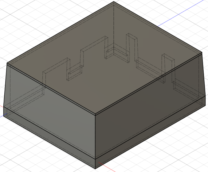
Case
I used some cable wrap for my AIN cables and made my 3D-printed case so that you can lift it off without undoing cables. Note the images are not the latest version.
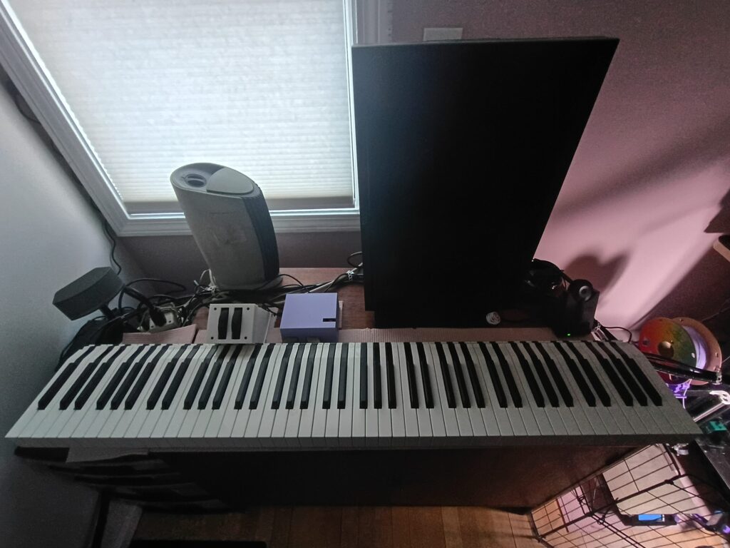
All together now
Leave a Reply